Technical Data – Modular Gauge Specifications
We have included technical data for the Modular Gauge Specifications. To see all Mitchell Aircraft Technical Specifications, please see our General Technical Data Page. If you need assistance with other technical data requirements, please contact us.
Modular Gauge Specifications
Gauges are 1-1/2 inches square
All gauges plug in from the front of the panel
– Ease of Installation
– Ease of Diagnostics
– Ease of Maintenance
Gauges may be stacked horizontally and vertically
– Horizontal or Vertical strips
– Horizontal or Vertical blocks
– User-defined sequence within strips or blocks
Gauges are internally lighted
Gauges are mechanically keyed to prevent gauge insertion in the wrong location.
Panel cutout is defined as: dimension = (0.020 + (# Gauges X 1.520)) inches
Example: For a cluster 3 gauges wide by 2 gauges high
the vertical cut is (.020 +(2 X 1.52)) or 3.06 inches
the horizontal cut is (.020 +(3 X 1.52)) or 4.58 inches
Gauge mounting frames have a 1/2 inch flange around the periphery of the gauges for mounting the frame to the panel. Mounting holes are supplied by the user.
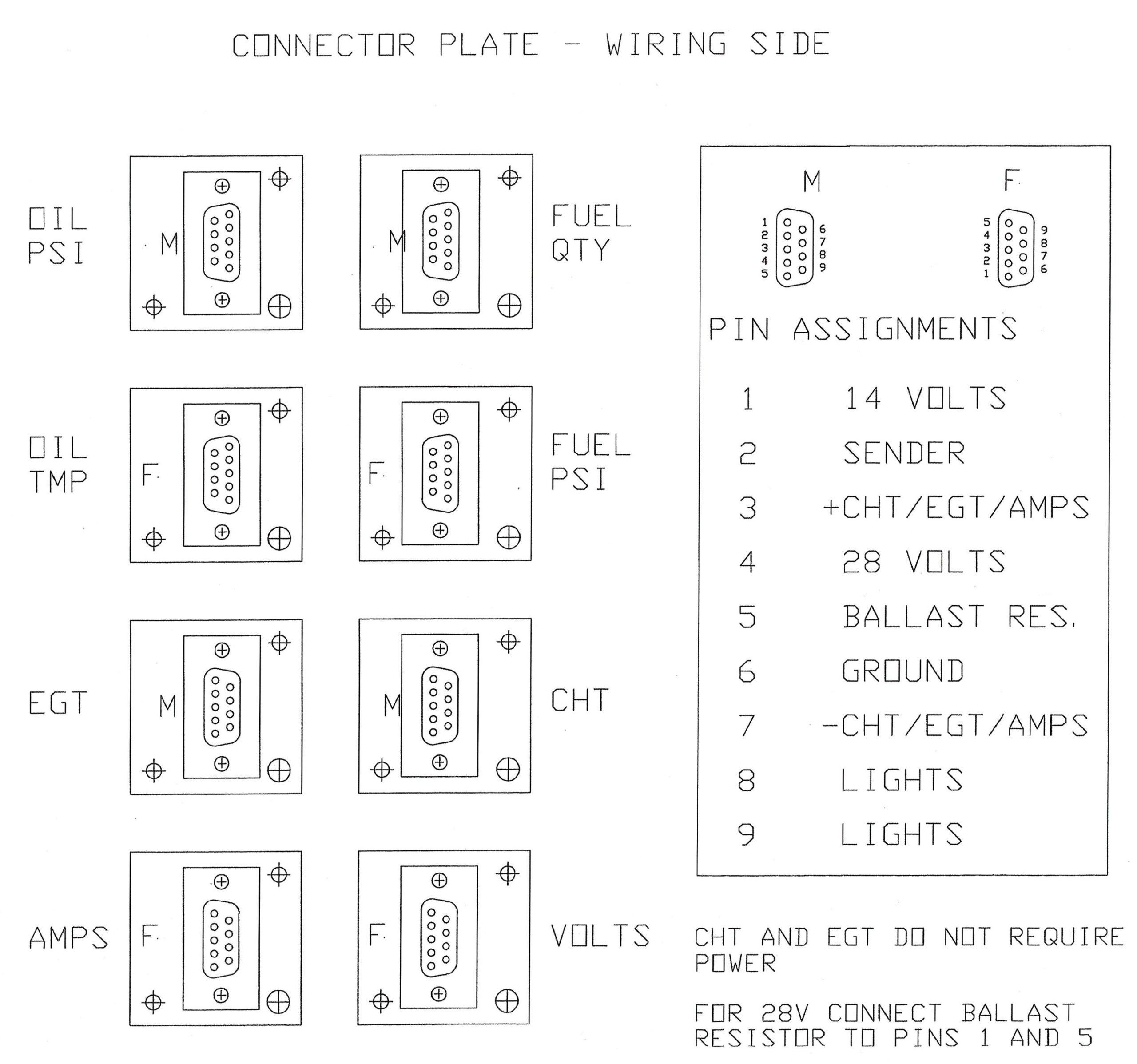
Gauges operate on either 14 or 28 volts. Power selection configuration is accomplished at the mounting frame connector. This must be specified at the time of order. Field conversion is not recommended and voids the warranty.
Gauge accuracy is specified as +/-5% of full scale.
Recommended depth behind the panel to clear the wiring harness is 4-1/2 inches.
Gauge wiring definition: